Announcement

Collapse
No announcement yet.

1925 JD Cannonball Bike

Collapse
X
 
  • Filter
  • Time
  • Show
Clear All
new posts

  • #16
    Thanks for the compliments guys. I've got a whole bunch more work of that nature to do yet.

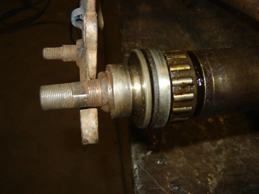
    Had a pleasant surprise recently. Here is a picture of my rear wheel not too long after it was removed from the frame. The wheel was stuck solid so I just figured that the bearling and hub were junk.
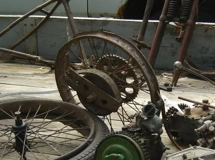
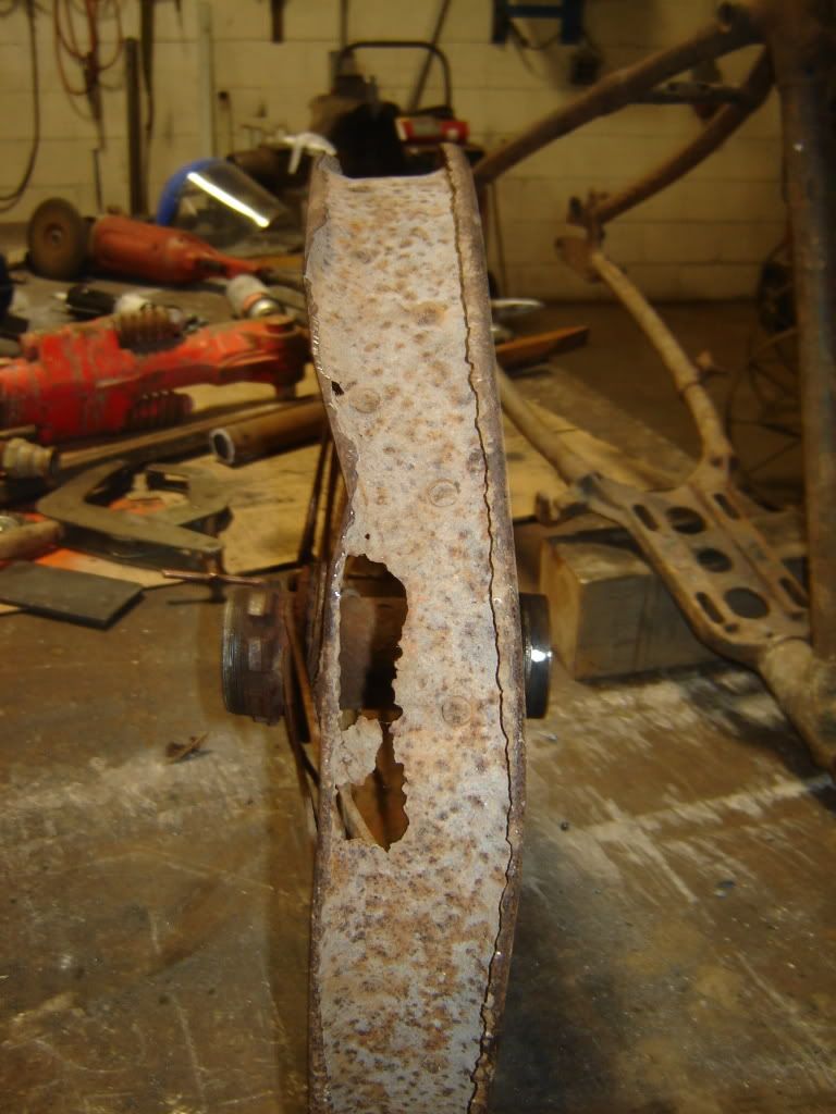


    I was a bit surprised when I got the brake removed that it actually spun and quite freely. The real surprise however was when I removed the bearings, axle and the axle sleeve. After 50 years of sitting out in a farmers cow pasture in northern Wisconsin, not a single drop of moisture had been able to penetrate the seals. Internally the hub was absolutely perfect and really show signs of having been a low mile bike. Lucky for me that old farmers probably ruined more stuff by over greasing than not - made an excellent cosmoline.
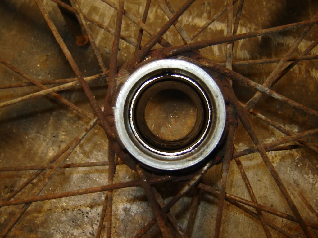
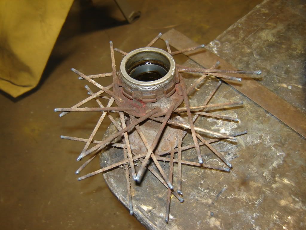
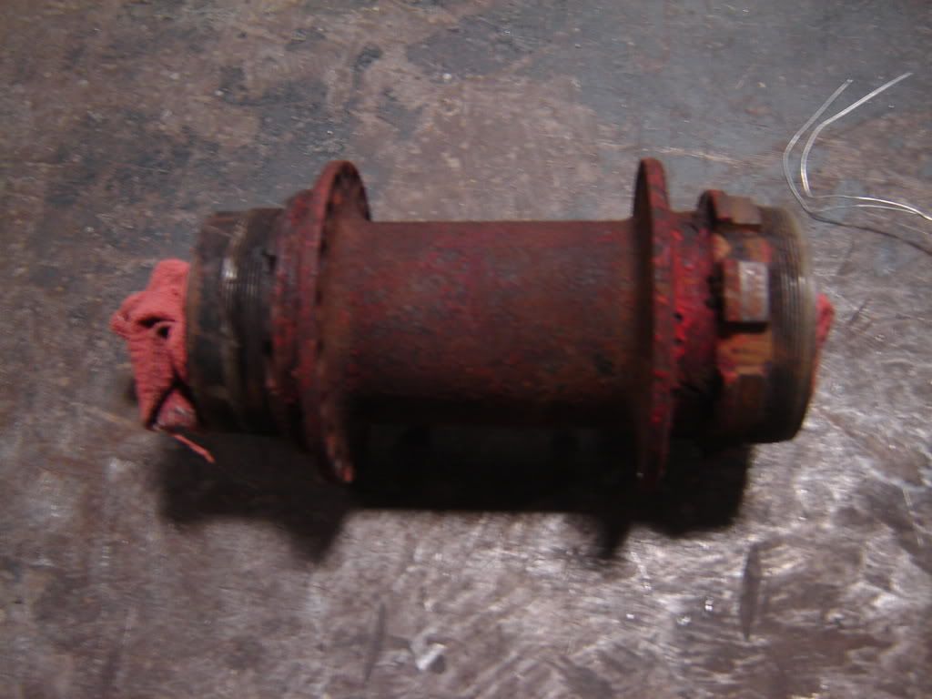


    I had actually purchased another wheel assembly from Tom Sheldon but now I will have a spare. I am going to lace the hubs up to 19" VL rims.

    Jerry
    Comment


    • #17
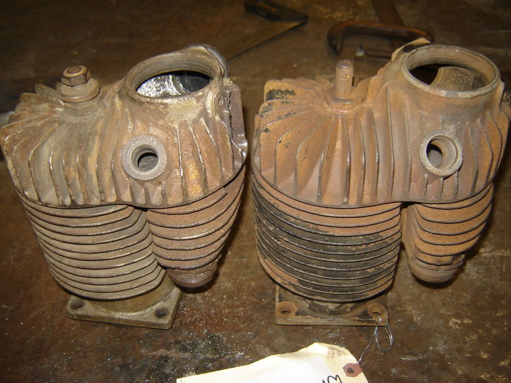
      Tonite I was back on welding fins on cylinders. This time on my spare cylinders which are off of a 1927. I came home from Davenport with almost everything I needed to complete the bike except good cylinders. I had bought a rear standard bore 1928 cylinder that had a wrist pin groove and that was all I saw for usable cylinders. I started watching ebay and found a new seller selling a JD motor with very poor pictures. I took a chance and and bought it and it turned out to be a mint standard bore engine.

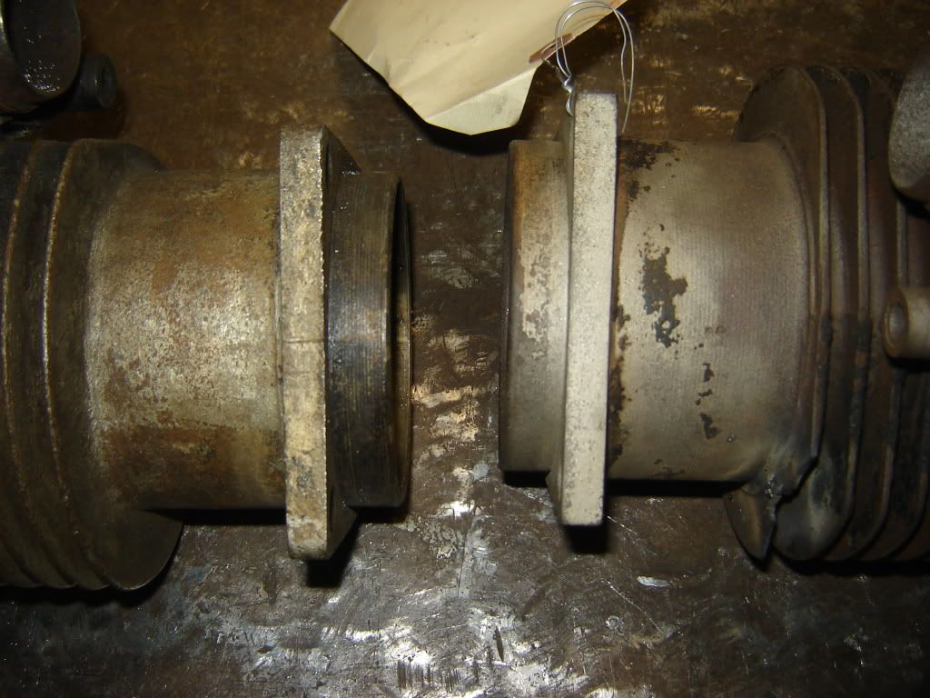
      The accepted differnece between a 1925/26 cylinder and a one year only 1927 cylinder is the sparkplug hole is smaller on the 1927. Tonight I happened to set the 1927 cylinder next to the 1925 cylinder and noticed a difference in the construction. The 1925 cylinders has a machined finish and the 1927 cylinder is raw cast.


      Just thought it was a bit curious.

      Jerry

      Comment


      • #18
        Jerry
        You'll also notice that 1927-1929 cylinders (the ones with the smaller metric spark plug hole) also have a radius instead of a sharp corner on the four corners of the base flange.
        Mark Masa
        Mark Masa
        www.linkcycles.com

        Comment


        • #19
          Mark

          That is actually part of what I was talking about. They squared up the flange and turned the barrel part of the earlier cylinders.

          Tonite I just about finished up welding on the fins of the 3rd cylinder. The 4th cylinder (1925 rear) with the double wrist pin grooves and the crack in the skirt I am going to send off to Midwest Cylinder Head and Machine in Nevada, Iowa. It is at standard but would probably take .060" to clean it up and with the crack fixed and the wrist pin scratches welded up it should clean at .020 to .030". Its' partner (1925 front) should clean up at the same.

          Midwest Cylinder Head and Machine are professionals and come highly recommended. I have seen quite a bit of their work and it is fantastic. I have never had them do anything of mine yet but have seen some of my friends.

          Nevada is just outside Des Moines and a trip there will give me an excuse to visit my brother and his family.

          Jerry
          Last edited by Jerry Wieland; 12-01-2011, 10:52 PM.

          Comment


          • #20
            If you knew how impossible it is to get correct spokes you wouldn't have cut those. :-(
            Be sure to visit;
            http://www.vintageamericanmotorcycles.com/main.php
            Be sure to register at the site so you can see large images.
            Also be sure to visit http://www.caimag.com/forum/

            Comment


            • #21
              Chris Those spokes were totally beyond hope. They were very deeply pitted and some had actually rusted off. I would never have destroyed anything that was usable. I would never have trusted those spokes on a ride around the block much less one from NY to SF.

              Comment


              • #22
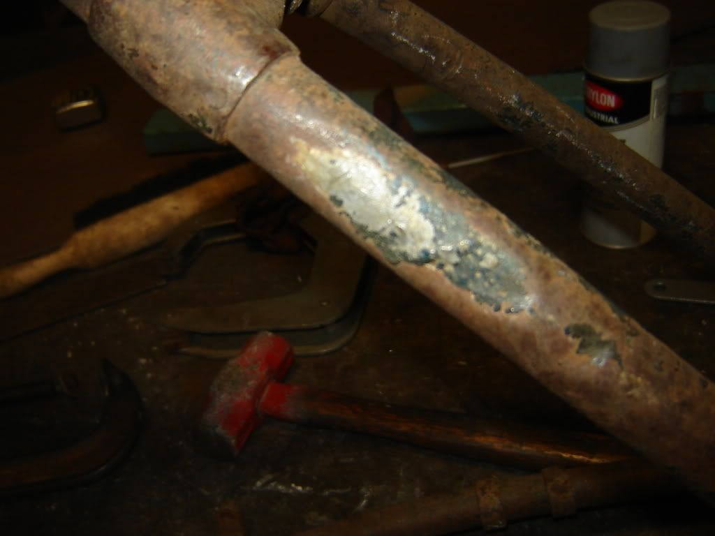
                I am just about done with repairing fins on 2 sets of cylinders but I have to tackle some frame issues while an opportunity presents itself. One of the millwrights at work has volunteered to lasor in my frame on Thursday evening so I need to get a couple of things cleared up. I was thinking that I only had 3 issues with the frame but one of them got a little uglier tonight.

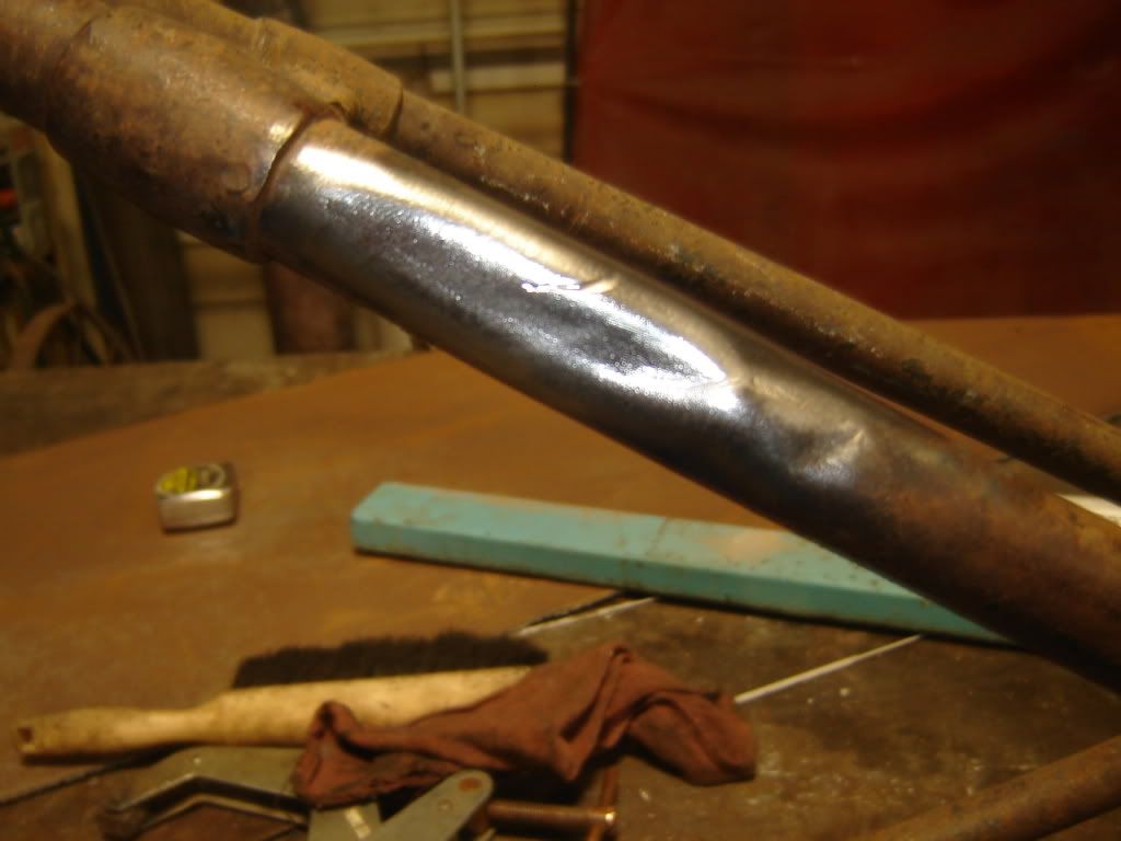
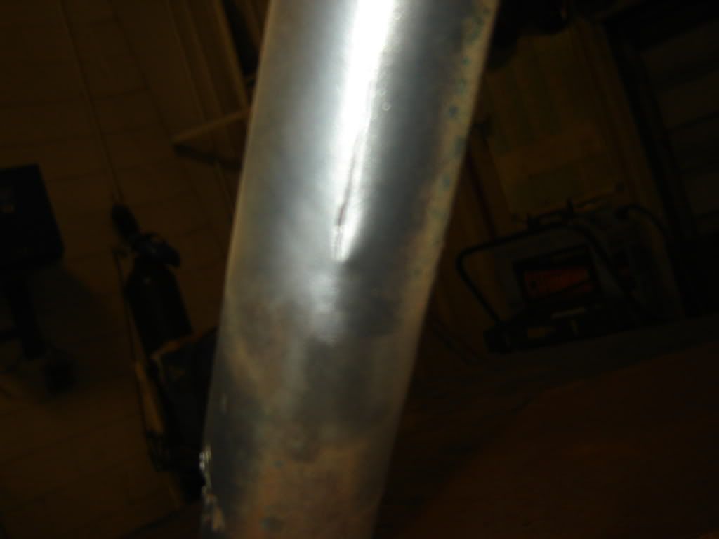
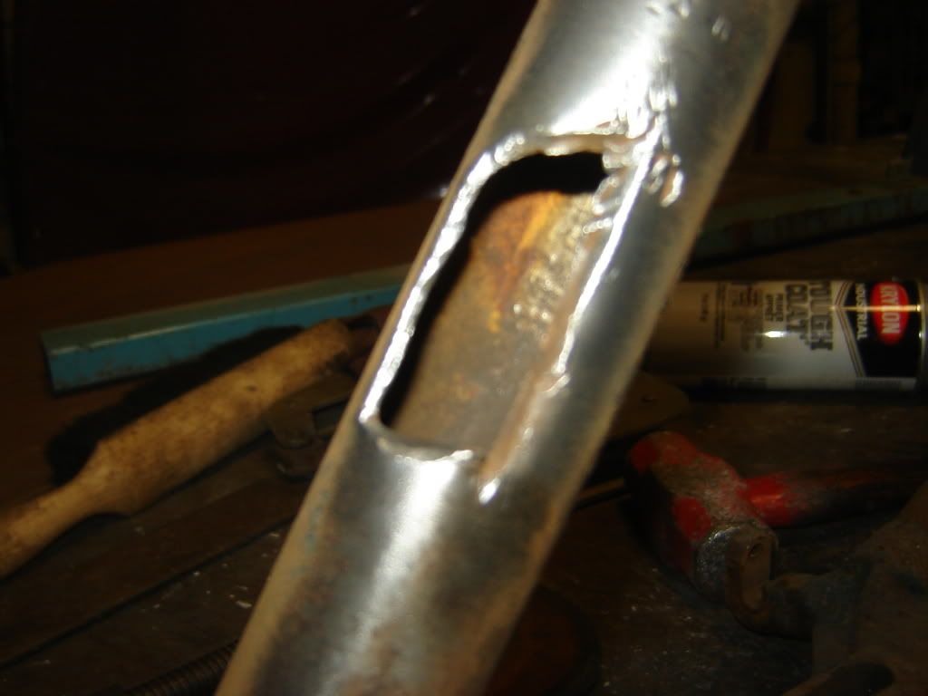
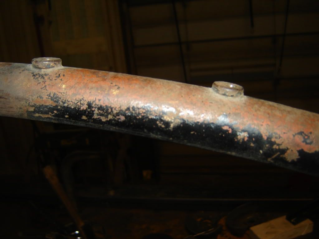
                This is a picture of the leftside upper frame stay that I thought was just a dent that someone has filled with body lead.


                After I cleaned it up, it appeared that the tube had been ground away and that is what I found when I used an ultrasound thickness meter used for measuring pipe thickness. I was originally thinking that I would be able to pull out the dents by welding a stud to the dent and using a slide hammer but now it looks like a partial tube replacement is in order.


                The other damage is further back on the leftside rear frame stay which appear to be shoved in about a 1/2" and the seatpost where I have a frost crack and someone needed a small chunk of steel for something else.


                You can see the issue when you look at the axle and how much it needs to go.


                I will post more later when I find the results of the lasor check

                Jerry
                Last edited by Jerry Wieland; 12-14-2011, 04:10 PM.

                Comment


                • #23
                  Can anybody verify that the rear wheel on a JD runs centered on the center line of the frame. That seems to be the case from what I am seeing but it would be nice if someone could confirm ot rebut that.

                  Jerry

                  Comment


                  • #24
                    I will check my '27 tonite for you. Are you looking for a quick visual, or do you want the verniers broken out? No problem either way.

                    Cheers,

                    Sirhr

                    Comment


                    • #25
                      Sirhr I do not know if we need a vernier but an accurate measurement of some sort with a ruler would be great. If the frame is bare I usually like to lay a straight edge along the upright tubes parallel with the center line and work from there. On a complete bike that might be a bit tough. Maybe a visual is the best we can do. I also plan on getting the tranny done and work back from the sprocket. Tomorrow night the lasor will just be a survey of the frame to see what is obviously awry. We will mainly be checking the surfaces that have to be parallel or perpindicular to each other. Then using this info I will build some kind of a fixture to mount the frame so I can deal with the problems.

                      Jerry
                      Last edited by Jerry Wieland; 12-15-2011, 06:59 PM.

                      Comment


                      • #26
                        Very interesting watching your progress + methods, I and many others no doubt have frames + other parts with similar issues. Thanks for sharing.

                        Comment


                        • #27
                          Well - just got done using a machine setup lasor transit on my frame. Its' the old good/bad news but basically I was pleased with what we found. Sorry no pictures because cameras are not allowed in the factory where we were working on the frame due to some R&D work that is on going.

                          We set the transit up first to sweep the vertical forming a plane that is perpendicular to earth which allowed us to then crudely fixture the frame with its center line being in a parallel plane to the transit sweep - this is easier said than done but we achieved our goal after about an hour. We set the centerline of the frame 6" from the "red wall" that the the lasor formed when it was spinning fast. It was setup in this manner so that we could measure from the lasor sweep to any part of the frame that we chose from the right. We chose that right because that allowed us to easily get to the critical areas of the motor mounts. I used a neck pointer that I had made out of 3/4" shafting and made bushings that fit snuggly in the neck.

                          We could either use a ruler and eyeball where the lasor passed or he had receivers that could be attached to the desired area and then would spit out the measurement in thousandths (or metric if you so wanted). The receivers were much more accurate than the ruler and eyeball.

                          You had to be careful with the number that you come up with because the measurement is to the outside of the tube but in fact the number you need is to the center of the tube so we were constantly adding or subtracting half the diameter of the tube or shaft.

                          Then we turned the lasor so it would sweep the horizontal. Here we had a "red ceiling" and measured down to the areas of the frame we wanted to measure.

                          This is what we found. The left frame stay is .080" lower than the right stay. This makes perfect sense because the upper tube has been bent and somewhat straightened. Any tubing I ever bent stretched on its' outer radius and in the straightening process usually grew in length and this is probably why this stay is lower. The right stay is exactly 4" from the center line of the frame and I believe that is correct. From an area 12" left and right of the transmission plate the variation was less than .030" which I would consider great. From an area 6" above the neck to 18" below the neck the variation was to the right by .125" and we never measured where it sat in comparison to the center line of the frame, that will come once the neck is perfectly vertical.

                          The rear motor mount was left of the centerline of the frame by approximately .500" which I believe is right because the thickness of the engine mount tabs is about .500" and this would place the parting line of the cases on top of the centerline of the frame. So far so good but here comes the part that kind of frustrates me. The front motor mount was .575" left of the centerline of the frame but when you measured to the tube it was perfect. This tells me that either it came from the factory this way or someone did an absolutely perfect job of removing .075" worth of cast steel from the mount and it shows absolutely no evidence of this.

                          I then looked at the cases and can see that the wear on the case mounts corresponds exactly with what you would expect this mismatch would do. Is it possible that the factory would have shimmed the motor originally and someone forgot to put the shim back when they removed and then reinstalled the motor?

                          Now I have to build a more permanent fixture so I can straighten it.

                          Jerry
                          Last edited by Jerry Wieland; 12-15-2011, 10:08 PM.

                          Comment


                          • #28
                            Jerry, I would guess it's entirely possible that a shim was forgotten. Either that or a factory worker had a little too much beer back in the day... Thank-you for taking us along for the rebuild ride. Very interesting stuff.
                            Cory Othen
                            Membership#10953

                            Comment


                            • #29
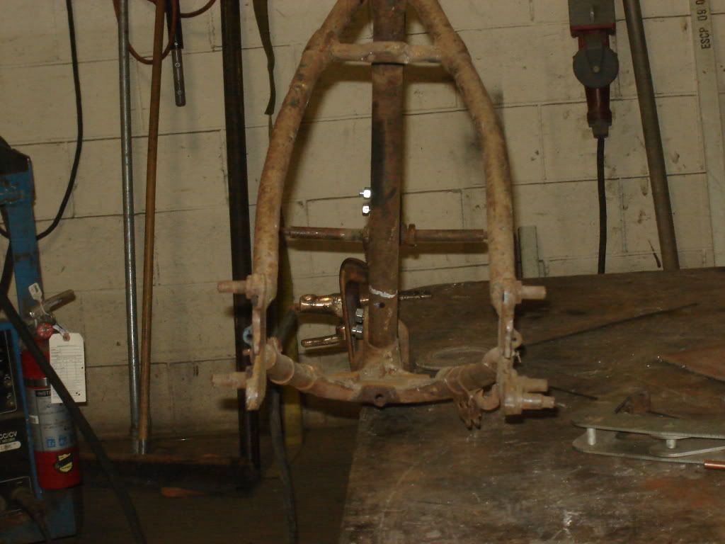
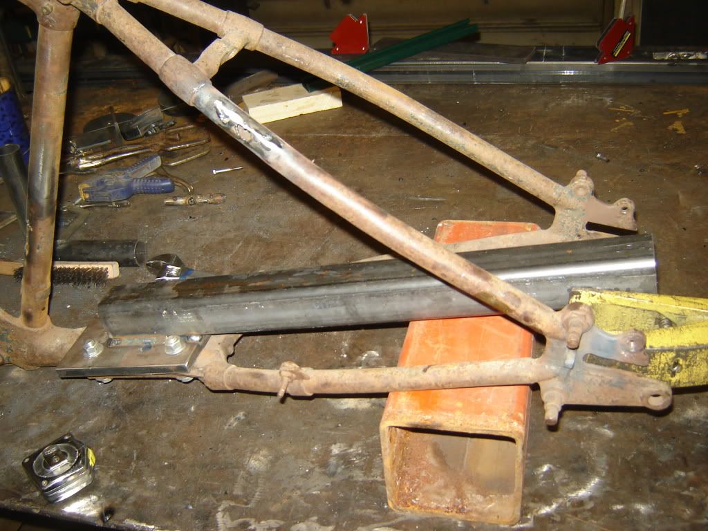
                              It has been awhile since I posted so I though I would post some pictures of some of the frame work I have done. After studying the frame and using the information that I got using the lasor transit I determined that the left rear frame stay was shoved inboard about 3/8" and that the right rear frame stay had a rotational twist to it - in other words the axle slot was not parallel to the leftside axle slot.

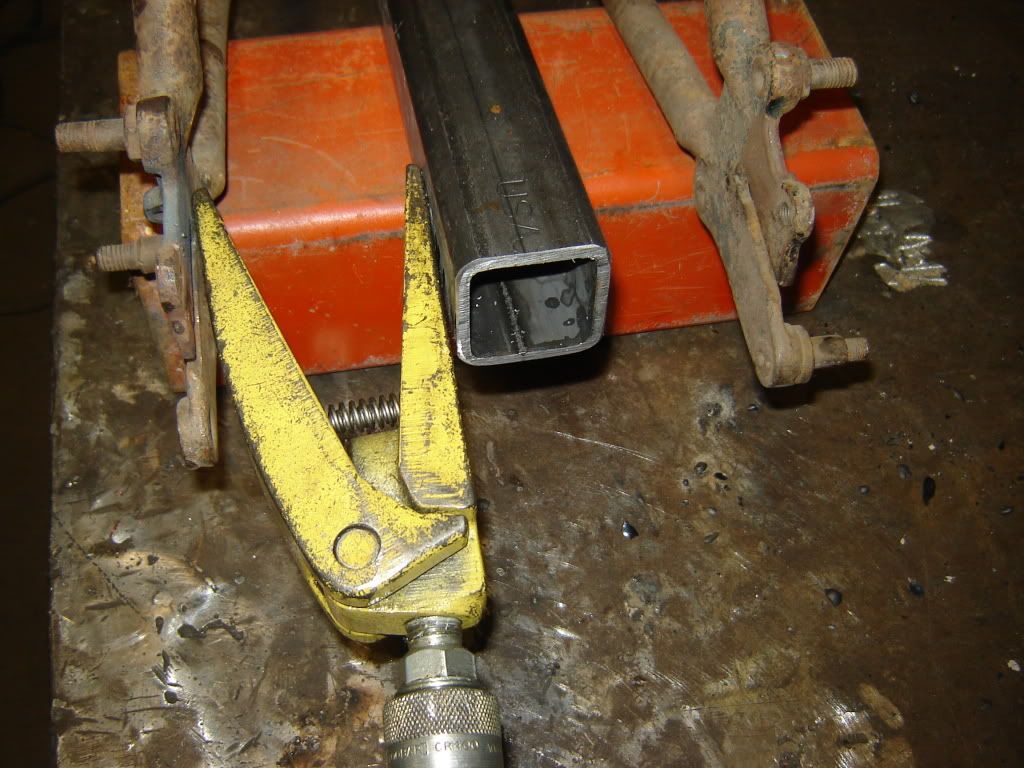
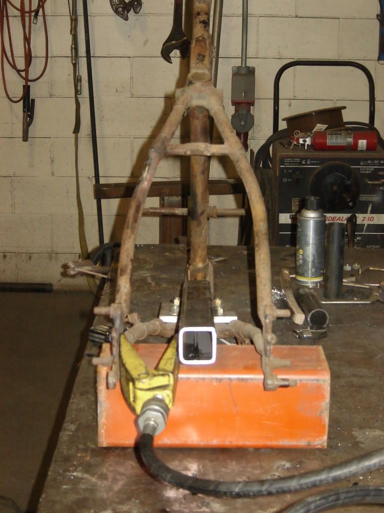
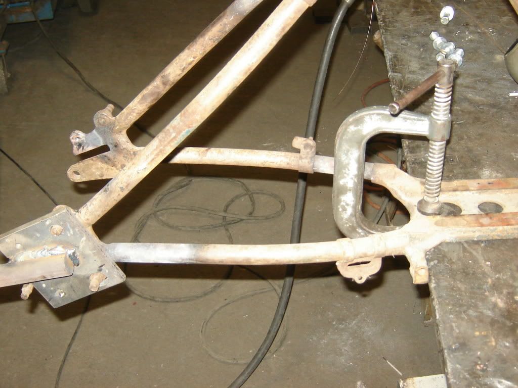
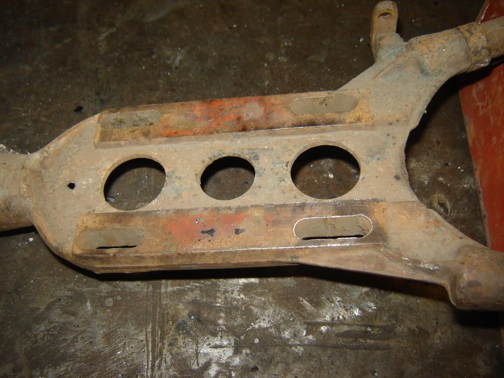
                              In order not to disturb the left/right position of the rightside frame stay, I built a fixture that bolted to the transmission mounting plate so that I could push against it to shift the leftside. I used a 'clam' that comes in most porta-power kits to actually do the moving. I still am not happy with the leftside upper frame stay tube because even though the frame stay is where I believe it should be the upper tube does not take quite the same mirror image path as the tube on the right side. I still prefer not to.

                              I used a very minimal amount of heat spread over a wide area. I would have preferred to bend it cold but it was not shifting exactly where it needed to.


                              To get the right side frame stay rotated back so the slot was parallel to the left side I built a tool with a 3' handle on it that bolted to the frame stay and then clamped the frame to my welding table, heated the lower tube where I could see the bend and then applied a little manual lifting force on the handle.


                              The only thing that remains to be seen with the frame is to see if the wheel tracks in such a position so that the transmission output sprocket tracks in line with the wheel sprocket. I have no blueprint to follow and nobody has come forward with any information to the contrary so I am assuming that the wheel tracks on the center line of the frame. When I get the transmission done I will have to do this check and then maybe move the frame stays left and right as a unit but hopefully not.

                              A funny thing here is that the more I play with the frame more I see of the red paint that it must have been painted when it was parked in the late 30's. The front end which was inside kept a lot of its' paint but not so much else.


                              More in a couple of days Jerry
                              Last edited by Jerry Wieland; 03-03-2012, 11:23 PM.

                              Comment


                              • #30
                                Jerry, I am enjoying watching your progress and look forward to seeing you and the finished bike and riding with you on the Cannonball.
                                Buzz Kanter
                                Classic-Harley.Info Classic Harley History
                                [Classic American Iron Forum Classic Harley Forum
                                [American Iron Magazine Harley Magazine

                                Comment

                                Working...
                                X