Announcement

Collapse
No announcement yet.

Ryan's A.M.C.A. Giveaway bike build!

Collapse
X
 
  • Filter
  • Time
  • Show
Clear All
new posts

  • Matthew N. Olse
    replied
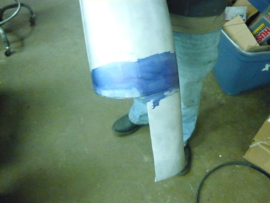
    It is snowing really bad over here in South Dakota again. It is supposed to get to -35 degrees tonight with the windchill factored in. Thankfully it is always 65 in the shop! Ryan bobbed his fender today. It turned out well. First he marked the center of the fender, and laid out the part that needed to be bobbed off!


    Then he made a template of it and cut off the other side.


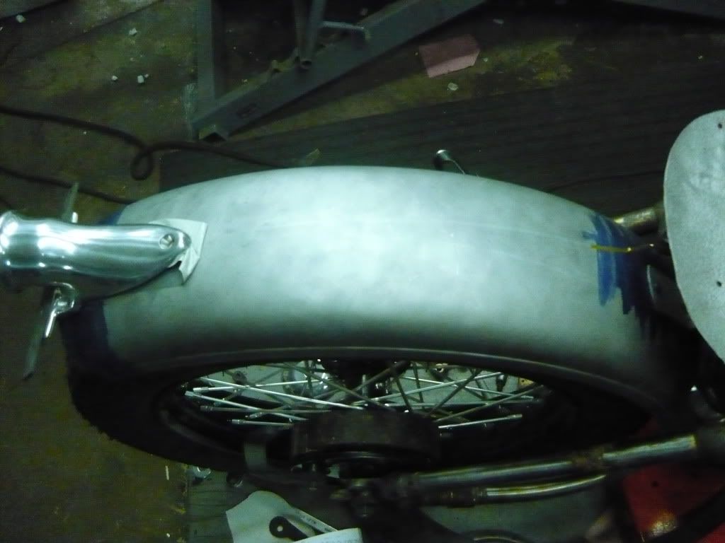
    Here it is on the bike with the tail light taped onto it to make sure the lense is at an angle that looks good.

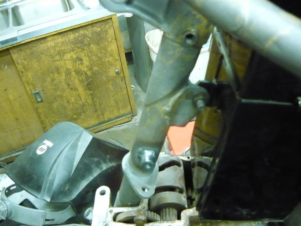
    I finished up his coil mounts on his frame. I used the existing hole for the grease zerc for the top bolt, and made up a tapped spacer for the bottom mount, It is .427 thick, if any of you plan on doin the same modification to your bike.


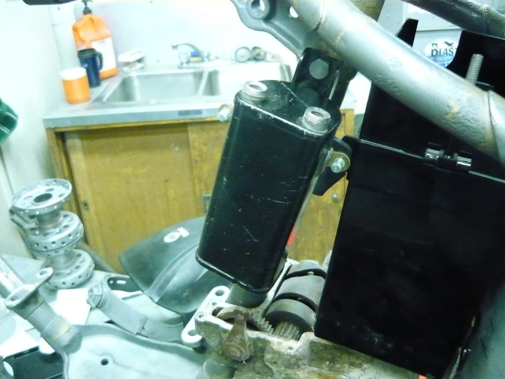
    Here is the coil mounted up to the bike!

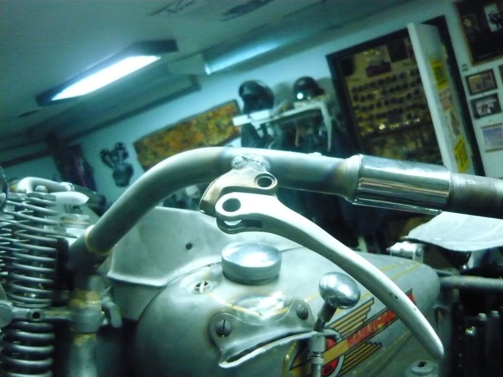
    Ryan wanted his brake lever perch welded to the handlebar. Luckily we had three and a half cast brake levers. We had an extra perch, so we gave it to Ryan to chop up. Here it is welded to the bar, it is a clean deal.


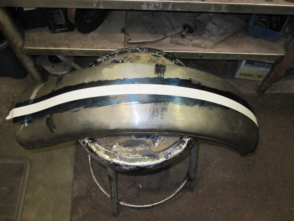
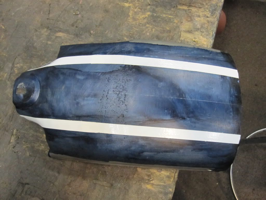
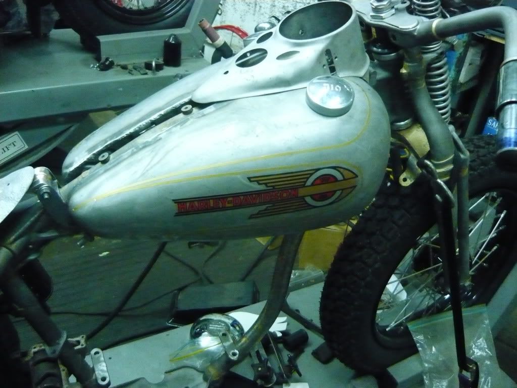
    We finished the night with a little practice in lay out. ryan is trying to figure out how he wants to paint his bike, here is the initial lay out. What do you guys think?
    Leave a comment:


  • Matthew N. Olse
    replied
    Petri- Ryan used a 1/32 3m cut off wheel to chop up the fender.

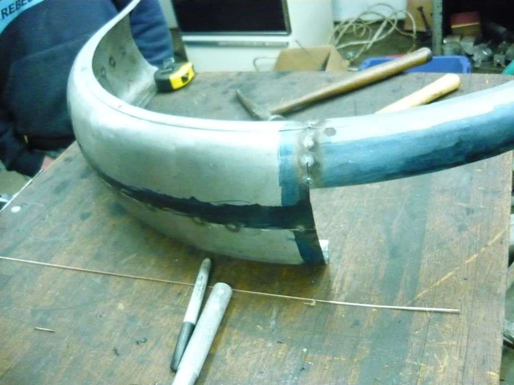
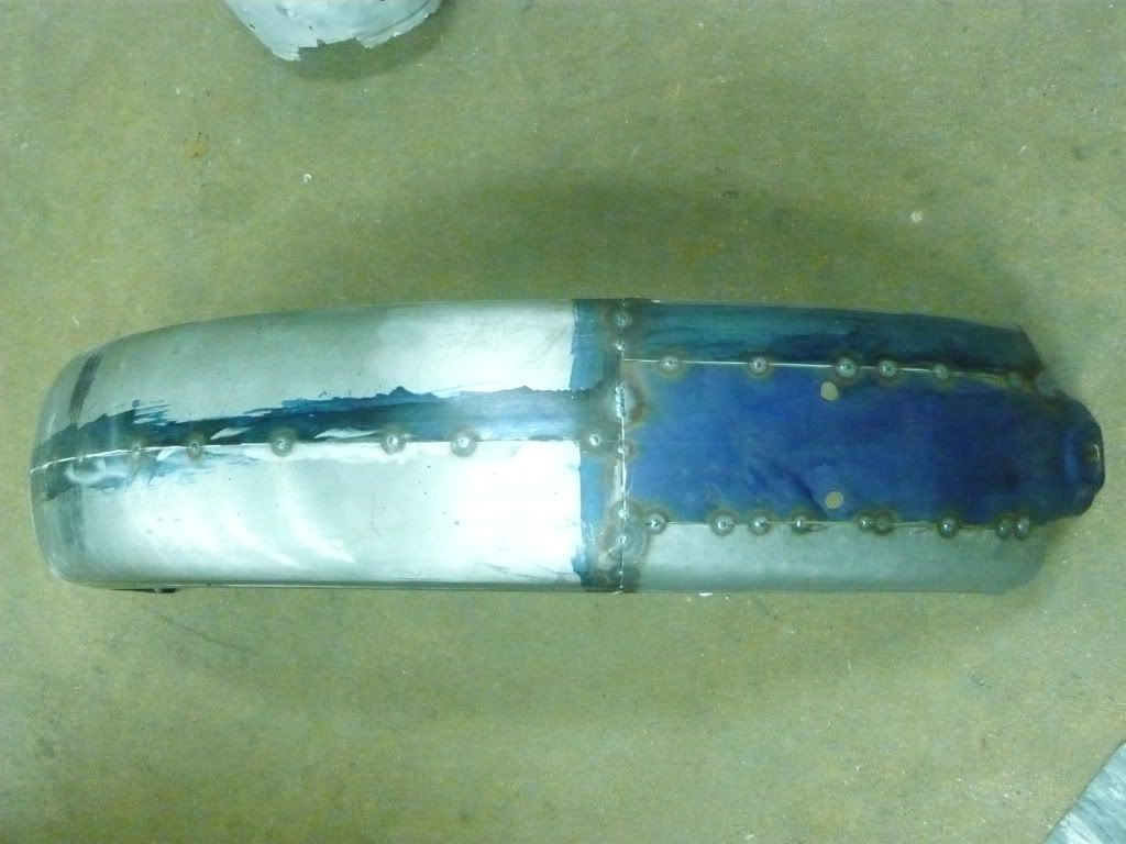
    Ryan spent the day getting the rest of the fender ready for welding. Here is a pic of everything tacked together


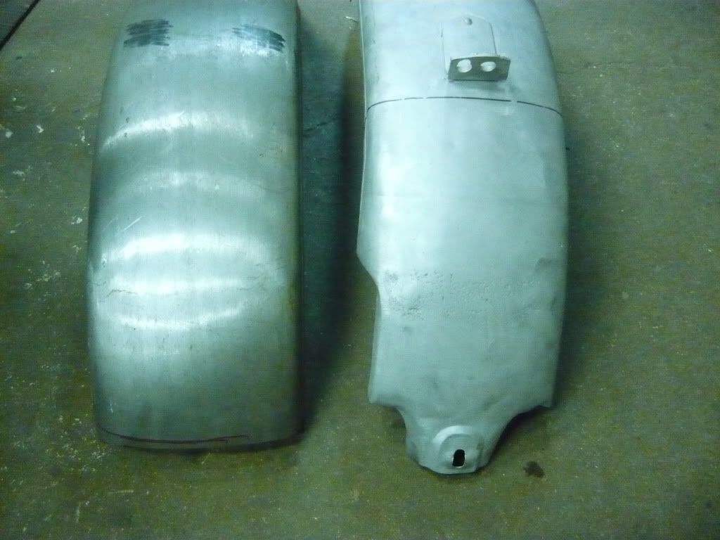
    Here it is after being welded back into one piece. I set it next to an o.g. fender so you could see what a difference 1 inch makes.


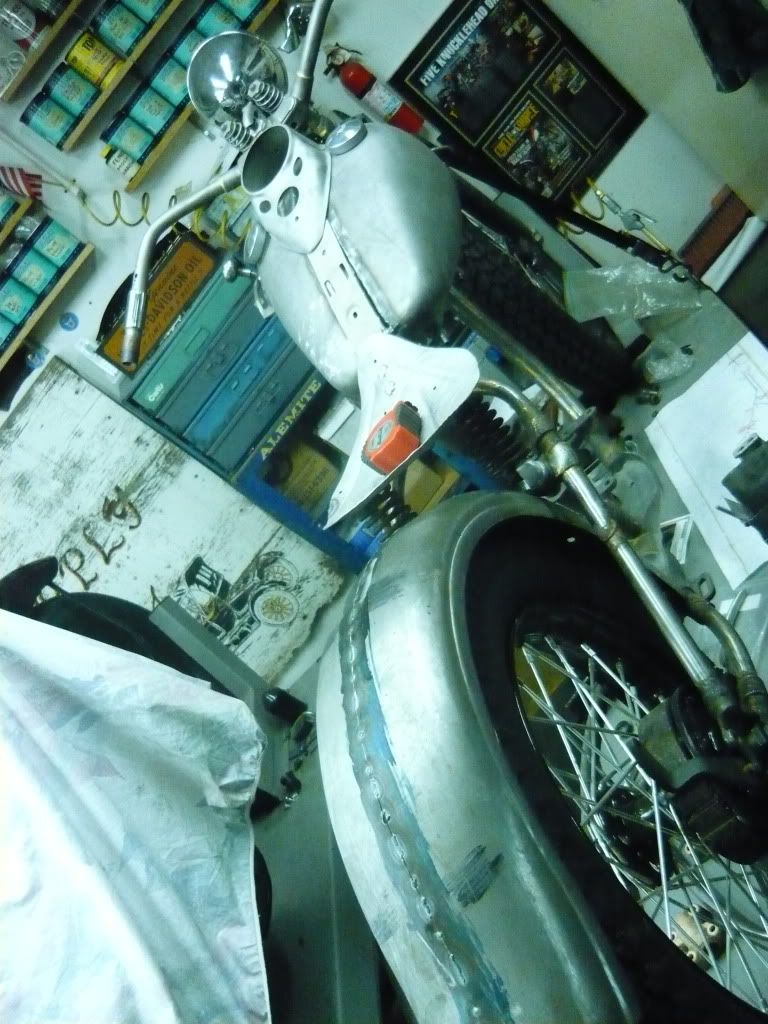
    Here is what it looks like just sitting on the bike. Ryan still has to sand the welds and do a little bit of straightening before we move onto the braces and skirts. Have a nice night!

    Leave a comment:


  • petri
    replied
    Just curious as I don't think you mentioned it. Did you use a die grinder to cut the fender or something else?

    Thanks for the great thread and wonderful information.

    Howard

    Leave a comment:


  • rbenash
    replied
    Fantastic job in reporting an posting this project. Thorughly enjoying going over the details. Great photos and descriptions of activity. Ryan - I'm envious. Reminds me of working in my father's shop when I was a kid. Suck up all the info and experience you can. Great way to spend 5 weeks!

    Leave a comment:


  • Ryan Mackey
    replied
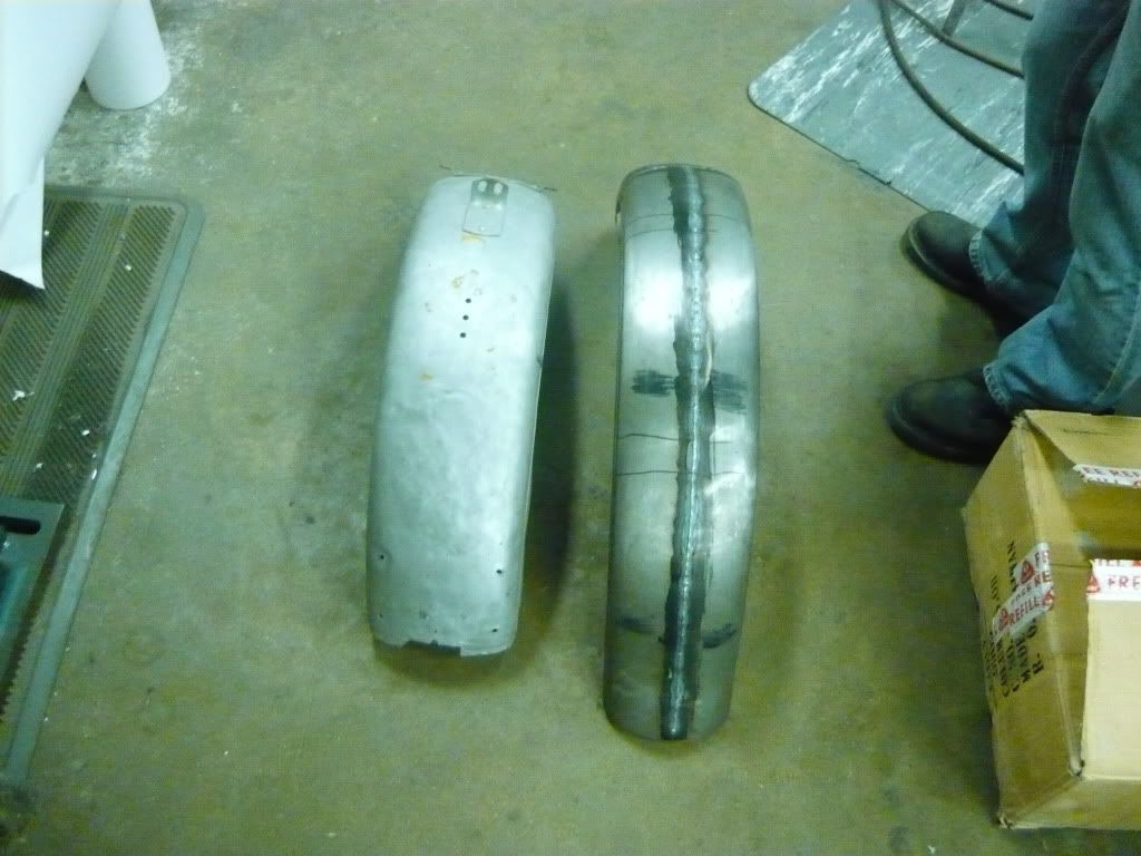
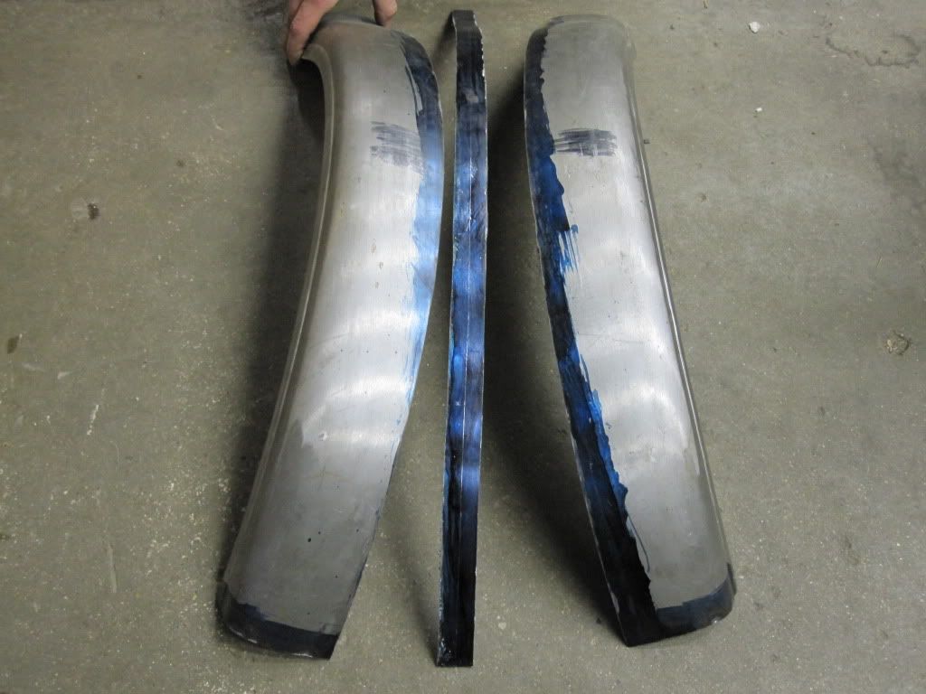
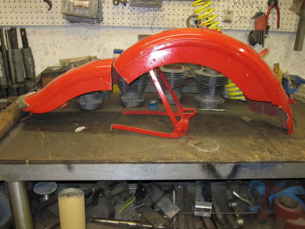
    Well this morning after talking with Matt and Carl, we decided with the rot on the fender, that it would be best to use a repo fender and cut and weld the mounting section onto it. The repo fender is on the left and the section we need to weld on is on the right.


    After I got it all cut and we tacked it in place, we set it on the bike to take a look. It looked to wide to me so I decided to section it 1 inch! I cut the tack welds so they were 2 pieces again and started laying out where to cut. Here is the repo fender ready to get chopped.


    Too late to turn back now!


    And here is the mounting section layed out. I took a half inch off each side of the mounting hole but made sure to stay away from the radius.


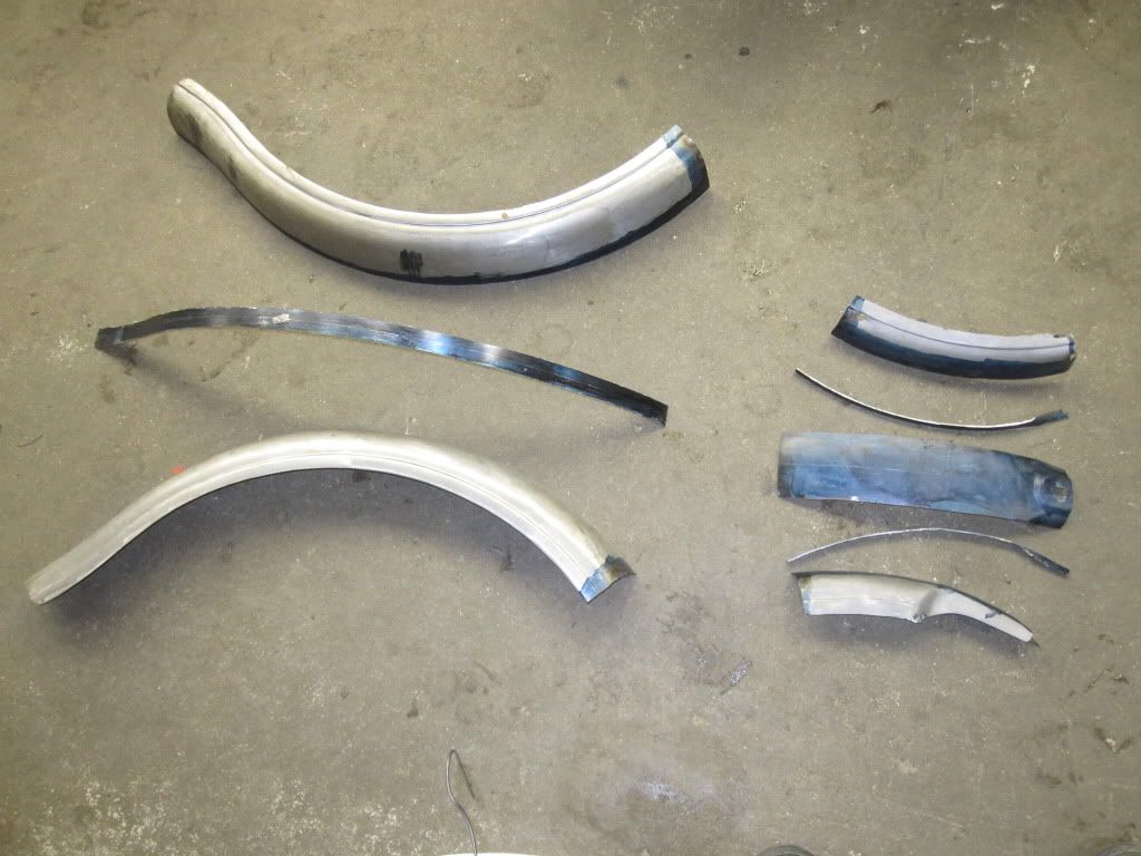
    A fender that was in 1 piece is now in 8!


    Here it is starting to come back together. The main fender is all tacked together, now it is just a matter of fitting the other section to match.


    There is still a lot of work left but I think it will make a huge difference on the whole bike.

    Leave a comment:


  • Ryan Mackey
    replied
    I started working on the rear fender tonight.

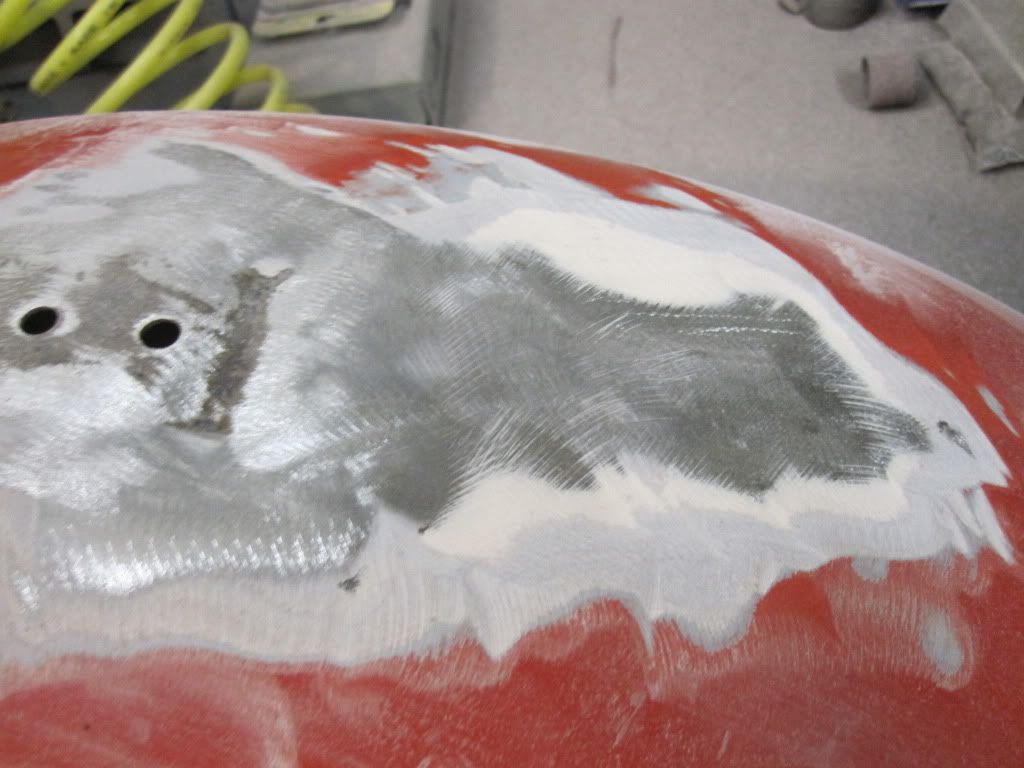
    I first sanded all the paint off, I was surprised at how much bondo there was in some places.


    Here it is after it was all sanded.


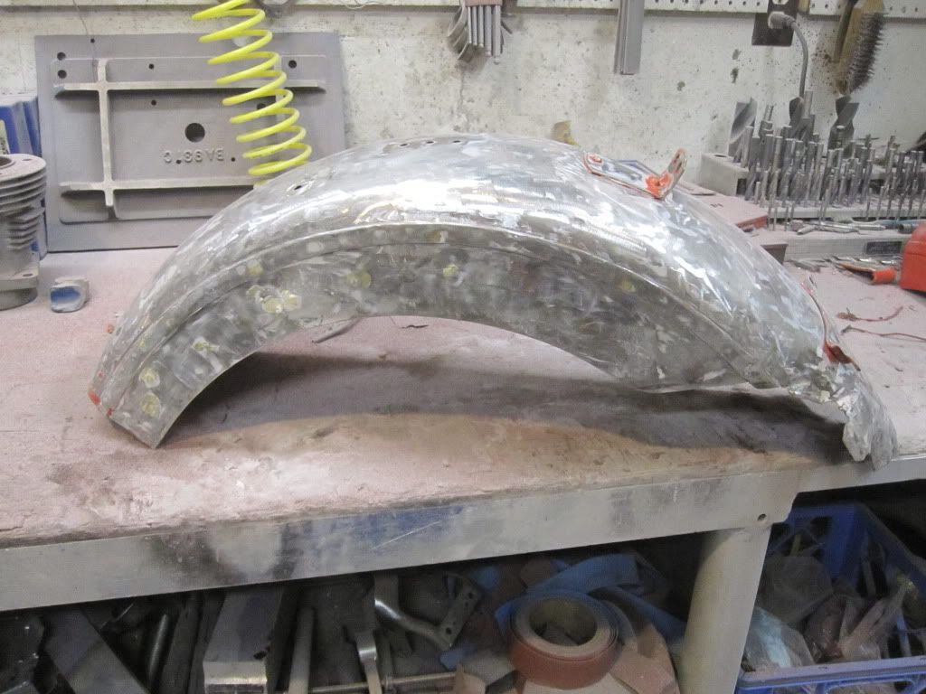
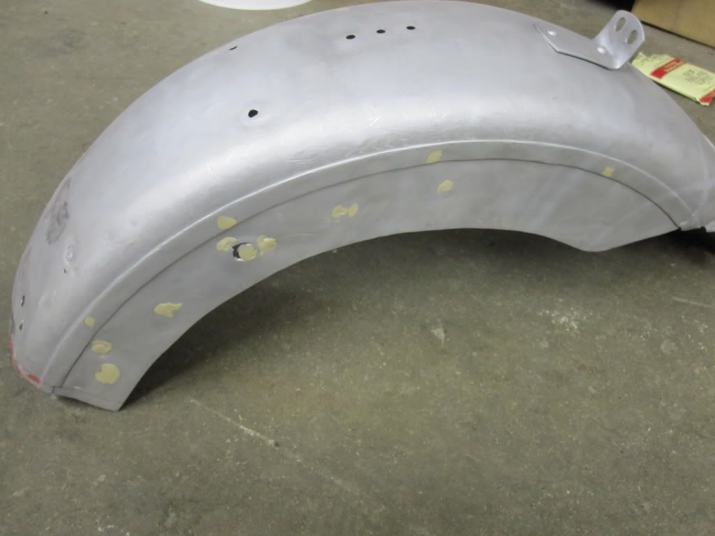
    And this is the fender after I bead blasted it. There are some rough spots but I am sure we can make something out of it.

    Leave a comment:


  • Slojo
    replied
    We defiantly elected the right man for the job.
    Joe

    Leave a comment:


  • c.o.
    replied
    Well ain't that a pretty site......... You guys are making a pile of headway in a short time!!!
    Leave a comment:


  • Matthew N. Olse
    replied
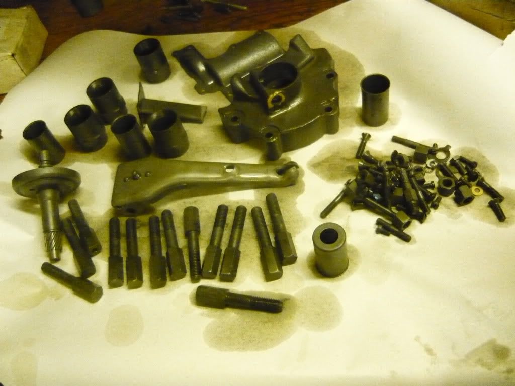
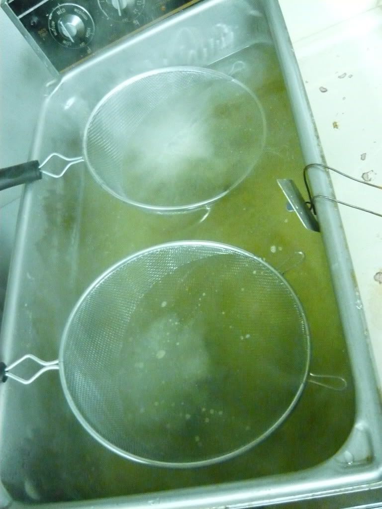
    Today we did a small batch of parkerizing for Ryan's Motor and transmission. Here is a pic of everything fizzling!


    Here is a pic of the batch after all the oil was washed off.


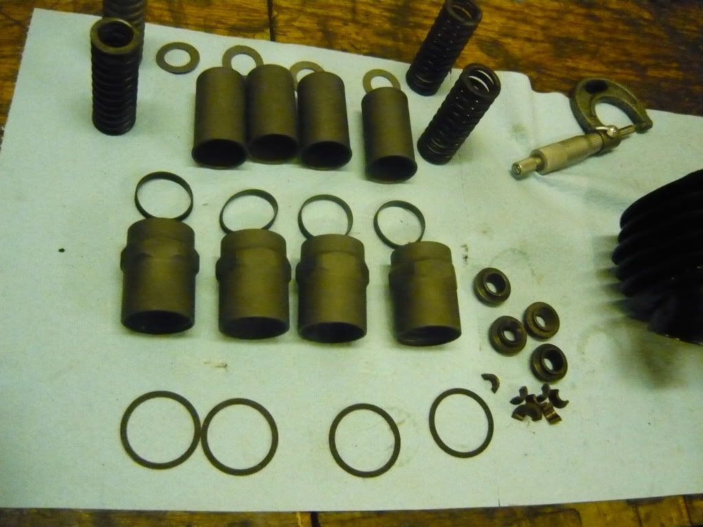
    These are the pieces that I was most excited to see. Valve spring covers were always cad plated from the factory. I have never seen a parkerized set before, and I really like the way they turned out.


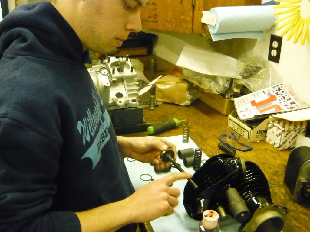
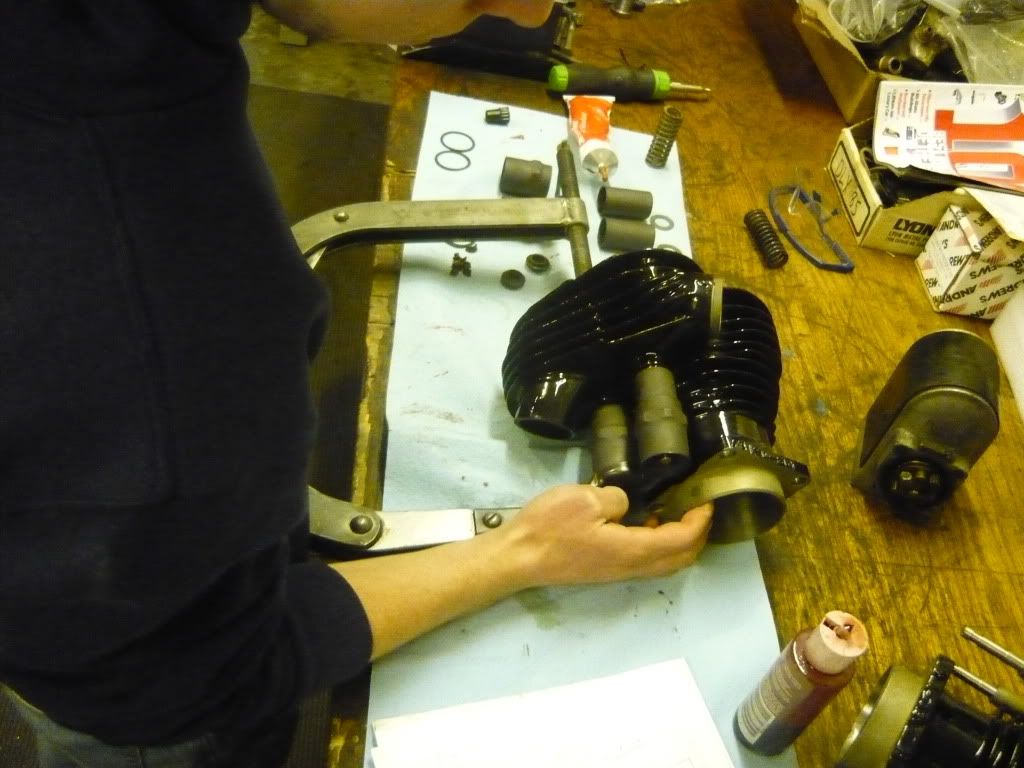
    With the valve covers parkerized, Ryan was able to put his top end together, Here he is lubing up the valve stem.


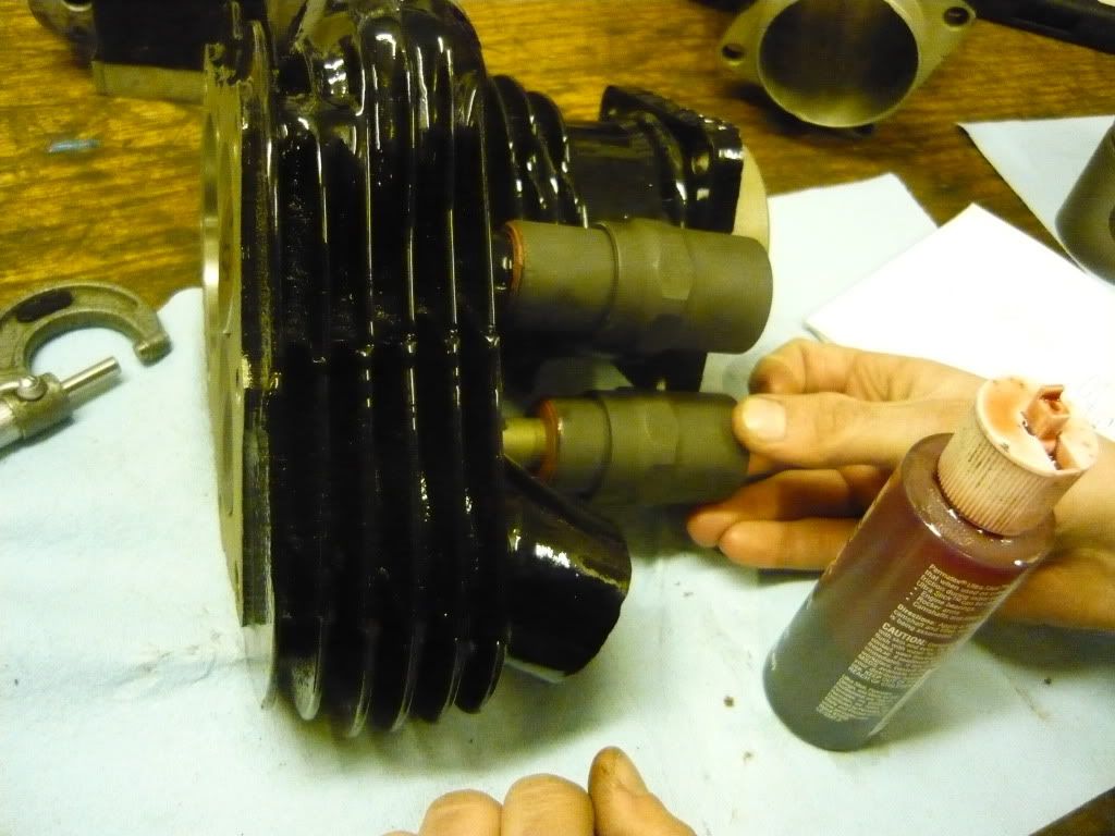
    We used 3m 800 to seal the surface between the valve guide and the upper valve spring cover.


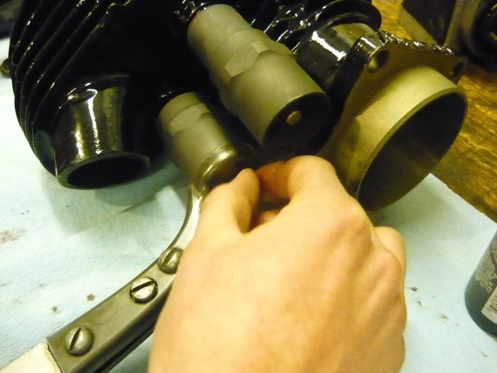
    Here is a pic of Ryan compressing his valve springs,


    And installing the keepers!


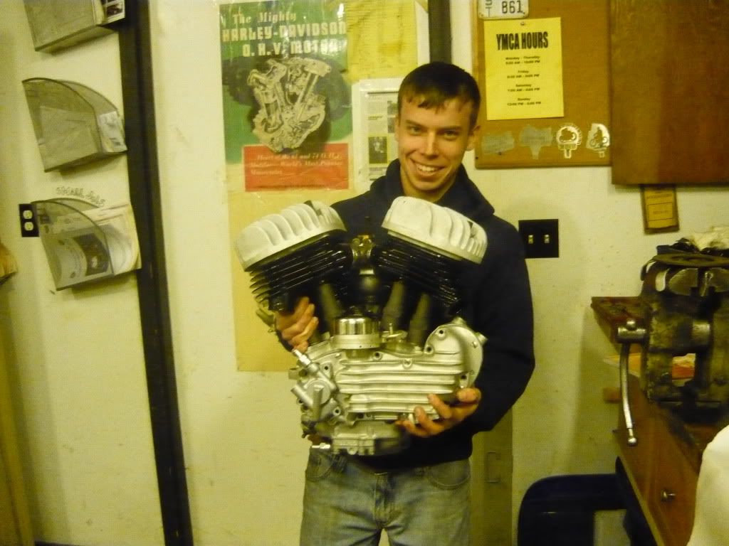
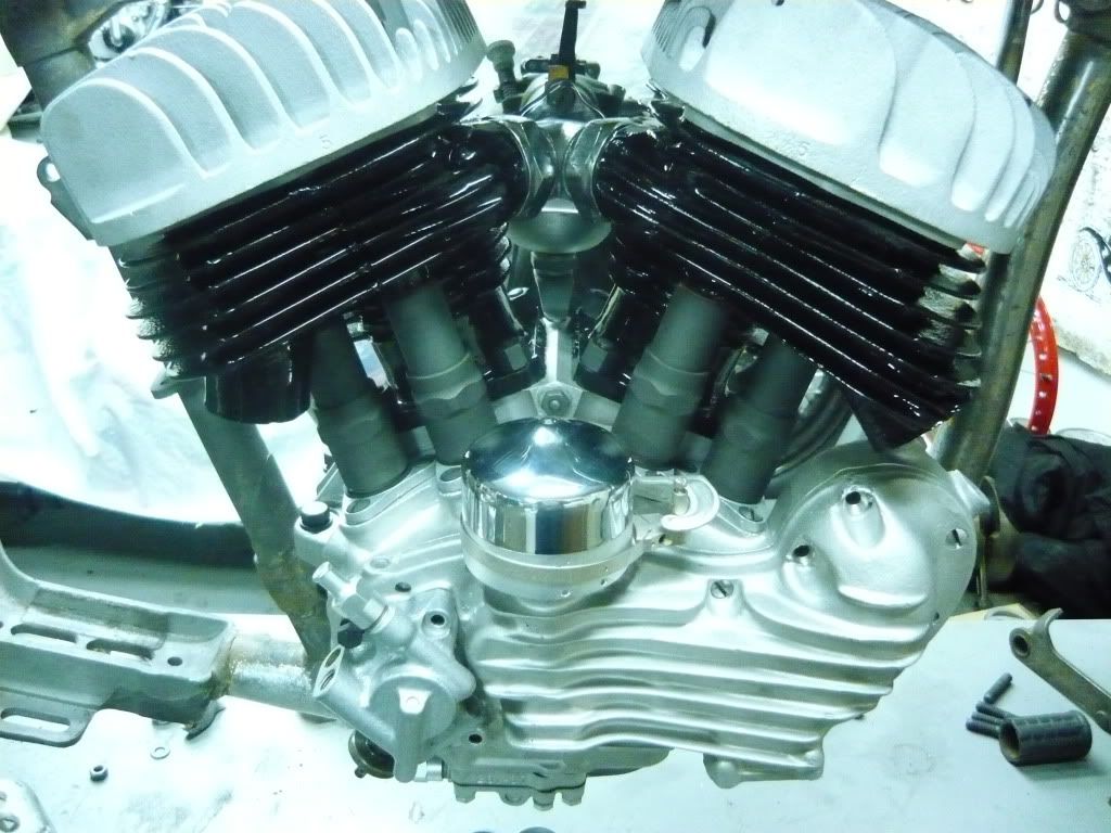
    Unfortunately we can not button up the motor until tuesday, which is the day that the n.o.s. flutter valve will show up from Scott. We couldn't resist mocking up the rest of the engine to see what it looks like. Here it is all bolted together! It is a really pretty sight.


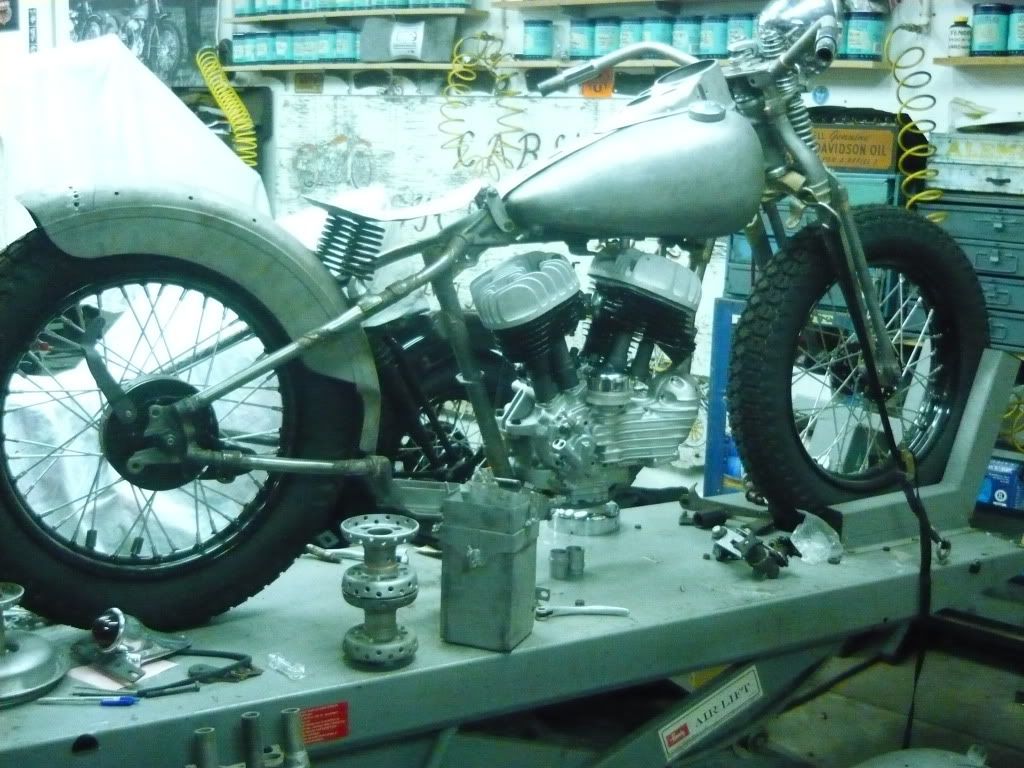
    And of course the next step was to throw it in the chassis.


    We are headed back out to work on the flatbed set up. Have a good night!

    Leave a comment:


  • Ryan Mackey
    replied
    Thanks guys for all the advice, I could use all that I can get.

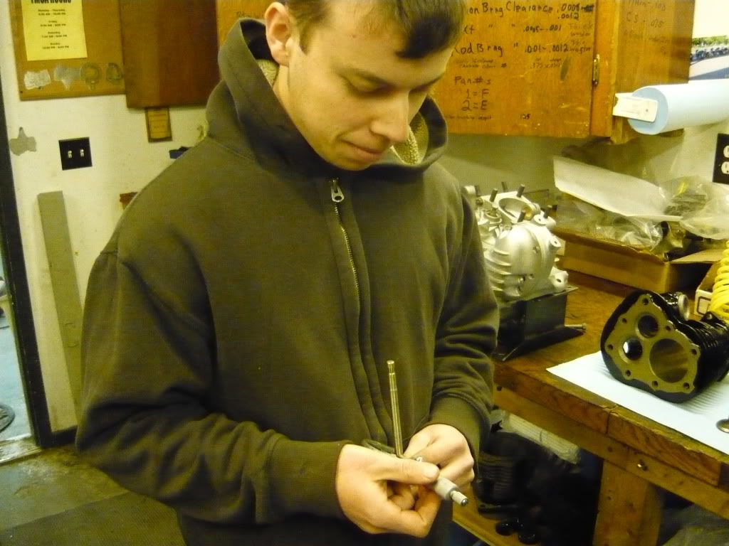
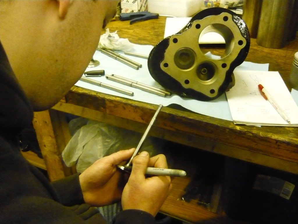
    It was -22 degrees out this morning when we got started...I thought Cleveland could get cold! We got some work done on the cylinders. The first thing to do was to measure the valves to make sure they were not worn. All four were really good. Here I am measuring them.


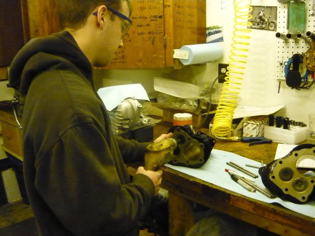
    The next step was to fit the valves in the guides. They were really tight and not within the specs so we had to hone them a bit. Here I am using a reemer to get them close.


    Then I finished them off by honing them.


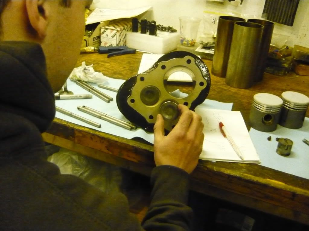
    After the valve fit nicely, I made sure that they seated properly. To do this I used a permanent marker and put four marks around the valve. Then I pushed them into the seat. They should leave even lines on all the marks, all four of my valves were good! Here I am putting the marks on the valves.


    And here I am pushing them in.

    Leave a comment:


  • Paps
    replied
    I can give ya a great finish using high speed steel, even at the lowest rpms. Tool grind and lube are the difference makers at low rpm with high speed steel tool bits. Though a finish may look nice and shiny with carb cutters and high rpm, what you really see is a glazing of the material. The surface is still rough. Using a profilometer surface finish unit, to gage the finish, will prove this out. If finish seems to be difficult to achieve on a lathe work piece, leave a little file and emery stock. For an example on finishes, one needs only to eyeball a newly honed cylinder. Cylinder wall looks rough due to the cross hatching but in reality, the finish is better than a 16f. OH YEAH.... Ryan....when using a file..... use only a file with a handle on it ! Keep file away from the front of you ! Do not force the file into the work piece ! Wire file brush the file teeth often ! Use the correct file for the job! Paps

    Leave a comment:


  • Slojo
    replied
    Matt, Private Ryan
    Ryan is outperforming my expectations he is doing a fantastic job. Understand first, my commentary yesterday was to help him along not discredit his accomplishments. He is welcome into my shop any time to further advance his skills.
    Joe

    Leave a comment:


  • Matthew N. Olse
    replied
    Joe,
    That is very good advice. Ryan used a high speed steel cutter, I think that he is doing pretty good considering that he didn't know how to turn a lathe on three weeks ago. Today we are going to cut valve seats, and then work on fabricating a flat bed set up for the cannonball run. Ryan is planning on riding his 45 along for the race next september. I am excited to have him be a part of it. Wish us luck, I am sure today will be another fun day.
    best,
    Matt Olsen

    Leave a comment:


  • Slojo
    replied
    Machinist Private Ryan

    Private Ryan
    The arbor turned on the lathe to repair the valve spring covers could have a better finish if you increase the speed and depth of cut a little. Spindle speed factored by the diameter of the work piece produces what is known as surface feet. By increasing your surface feet the steel will be happier to peel off leaving a better finish. Are you using high speed steel or carbide to cut with? High speed steel generally is limited to about 100 surface feet on common steel. Modern carbide will permit surface speeds of 500 or more. High speed steel is not as easy to produce good finishes as carbide. It is my understanding that the momentary heat generated at the tip of the cutting tool is necessary to produces a good finish. Higher speed equate to higher heat. Sharp tools properly honed are also factors in producing good finishes. To better understand surface feet and how it affects the finish, face off a piece of solid steel stock in the lathe. Start with a larger diameter, say around four inches and set the spindle speed high maybe between 500 to 800 rpm. Now take a small face cut from the outside to the center and watch how the larger diameter area leaves a better finish that the area closes to the centerline. There is a greater amount of surface feet generated at any given RPM at the larger diameter. You will achieve a better finish there than close to the center of the facing operation. The trade off is if you run the surface speed to fast you will burn up the cutting tool and possibly work harden the material if it has enough carbon content.
    Joe

    Leave a comment:


  • c.o.
    replied
    Great job Ryan! I know this has been said before but there's more than one of us here that are a little green-eyed at the opportunity that you've been given. Having said that it certainly seems like you deserve it! Keep up the good work!

    Leave a comment:

Working...
X