 Tweet
Tweet
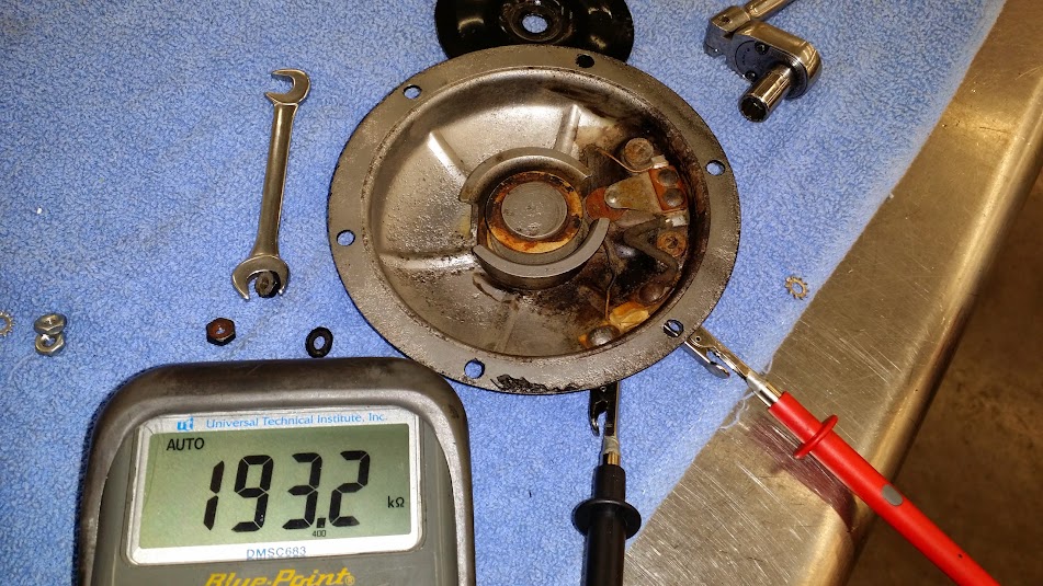
I was testing the electrical components of my fathers 35 VLD and found that the horn didn't work. I took a few measurements and discovered the horn had an internal resistance, between the posts, of almost 200k Ohms. A little out of the range of less than 0.5 Ohm recommended by Perry Ruiter.
I started with dis-assembly, fairly straight forward, 11/32" wrench or socket, except I have one nut on my horn that is 3/8", I will have to correct that later. At this time I also discovered that someone has been in here before, with a sand blaster. Crossed fingers in hope the coil isn't damaged.

I pulled the air gap screw out because I didn't research before taking the horn apart. There is no specification that I could find for this, so on assembly there was a bit of trial and error before getting it correct.
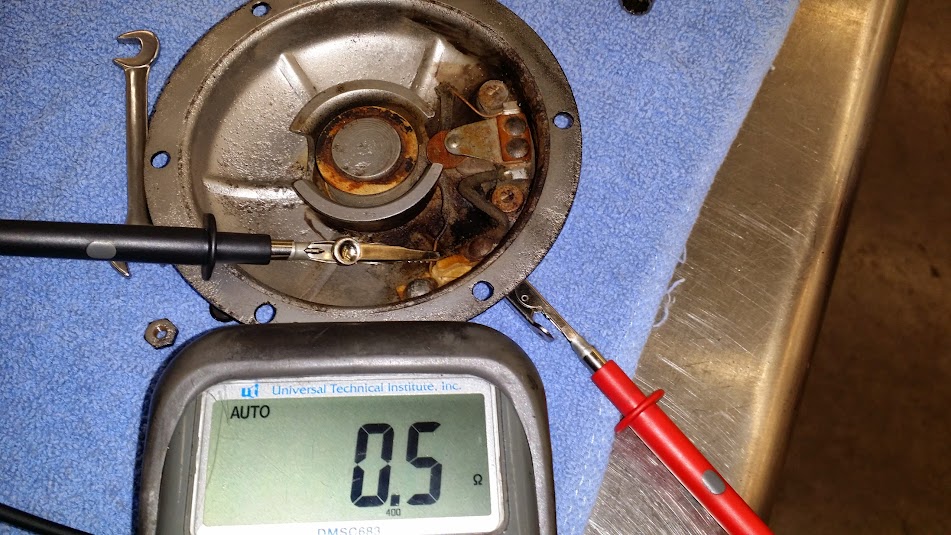
After removing the cover and diaphragm I cleaned the points with some emery paper and checked the resistance between the posts:
Still quite high. So I tested the components, starting with one post and moved throughout the horn until I found the problem. In this horn it turned out to be the other post itself!
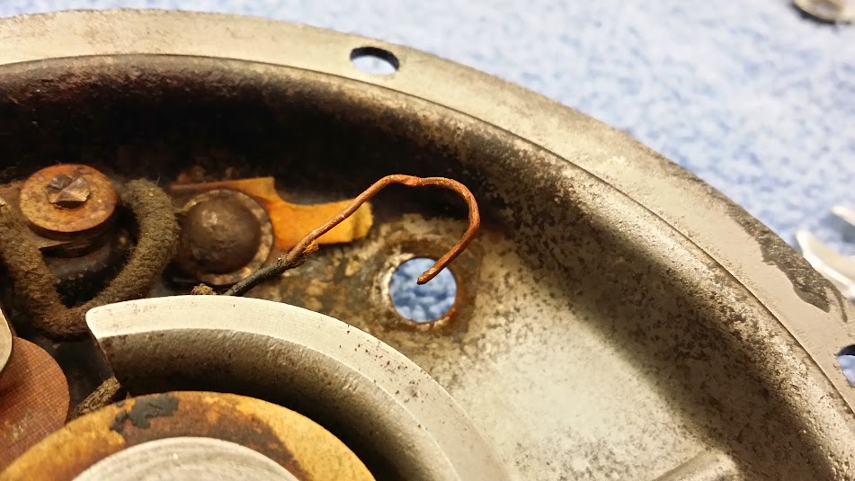
I am not sure if the bare wires at the posts should be as long as they are, but the extra length was nice and handy for testing.
After some fiddling with the post insulator material, removal without total destruction, I managed to get the post out and found the source of my high resistance.
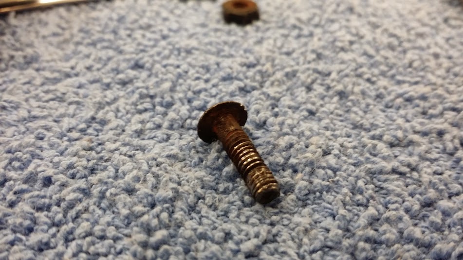
Some nice corrosion on that post! I am surprised that the wire was just wrapped around the post, no solder, nothing to give it a good mechanical connection. I am not sure if that is how they were made, or if it was something done during its previous cleaning and re-assembly.
After cleaning up the post, I soldered a loop onto the end of the wire for the coil, then soldered the loop to the post. A little dab of silicone around the insulator at the post hole in the housing to keep water out. Assembled the post into the horn, re-using the insulating paper and rechecked my resistance.
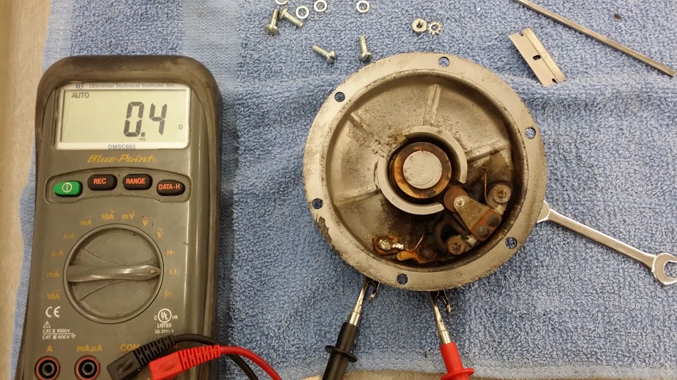
Hooray, less than 0.5 Ohms!
I assembled the diaphragm and ringer disc onto the front of the horn, setting the air gap screw to 2 turns out from touching the coil core. Then I adjusted the points adjuster so it was showing continuity when the diaphragm was not pressed, and open (infinite) when pressed with my thumbs. After a few adjustments it ended up sounding like this: https://plus.google.com/photos/10391...30323496803031.
My air gap ended up at 1 full turn out from just touching the coil core. Your mileage may vary. Also there is a metal post built onto the back of the diaphragm, this must be assembled so this is over the points so they are pushed apart when the coil is active.
I hope this helps some folks out there. If I have made any mistakes please let me know.
-Joe
Technical knowledge from the following:
Steve Slocombe: Buying, restoring, and riding a VL
Perry Ruiter Diaphragm Horn Overhaul Procedure
Bruce Palmer: How to Restore your Harley Davidson
I started with dis-assembly, fairly straight forward, 11/32" wrench or socket, except I have one nut on my horn that is 3/8", I will have to correct that later. At this time I also discovered that someone has been in here before, with a sand blaster. Crossed fingers in hope the coil isn't damaged.
I pulled the air gap screw out because I didn't research before taking the horn apart. There is no specification that I could find for this, so on assembly there was a bit of trial and error before getting it correct.
After removing the cover and diaphragm I cleaned the points with some emery paper and checked the resistance between the posts:
Still quite high. So I tested the components, starting with one post and moved throughout the horn until I found the problem. In this horn it turned out to be the other post itself!
I am not sure if the bare wires at the posts should be as long as they are, but the extra length was nice and handy for testing.
After some fiddling with the post insulator material, removal without total destruction, I managed to get the post out and found the source of my high resistance.
Some nice corrosion on that post! I am surprised that the wire was just wrapped around the post, no solder, nothing to give it a good mechanical connection. I am not sure if that is how they were made, or if it was something done during its previous cleaning and re-assembly.
After cleaning up the post, I soldered a loop onto the end of the wire for the coil, then soldered the loop to the post. A little dab of silicone around the insulator at the post hole in the housing to keep water out. Assembled the post into the horn, re-using the insulating paper and rechecked my resistance.
Hooray, less than 0.5 Ohms!
I assembled the diaphragm and ringer disc onto the front of the horn, setting the air gap screw to 2 turns out from touching the coil core. Then I adjusted the points adjuster so it was showing continuity when the diaphragm was not pressed, and open (infinite) when pressed with my thumbs. After a few adjustments it ended up sounding like this: https://plus.google.com/photos/10391...30323496803031.
My air gap ended up at 1 full turn out from just touching the coil core. Your mileage may vary. Also there is a metal post built onto the back of the diaphragm, this must be assembled so this is over the points so they are pushed apart when the coil is active.
I hope this helps some folks out there. If I have made any mistakes please let me know.
-Joe
Technical knowledge from the following:
Steve Slocombe: Buying, restoring, and riding a VL
Perry Ruiter Diaphragm Horn Overhaul Procedure
Bruce Palmer: How to Restore your Harley Davidson

Comment